Reconfigurable Hinged Kirigami Tessellations
We introduce a computational method for designing kirigami patterns that reconfigure flat sheets into complex shapes. By analyzing planar tilings and their rotational deployment, we identify valid cuts and generate novel, physically realizable structures. This enables inverse design of expressive, gap-free geometries through combinatorial reconfiguration.
Background
Note: The left image shows an example of a complete cut (black arrows). After making these cuts, the tiling can be transformed into a hinged kirigami structure example shown below.
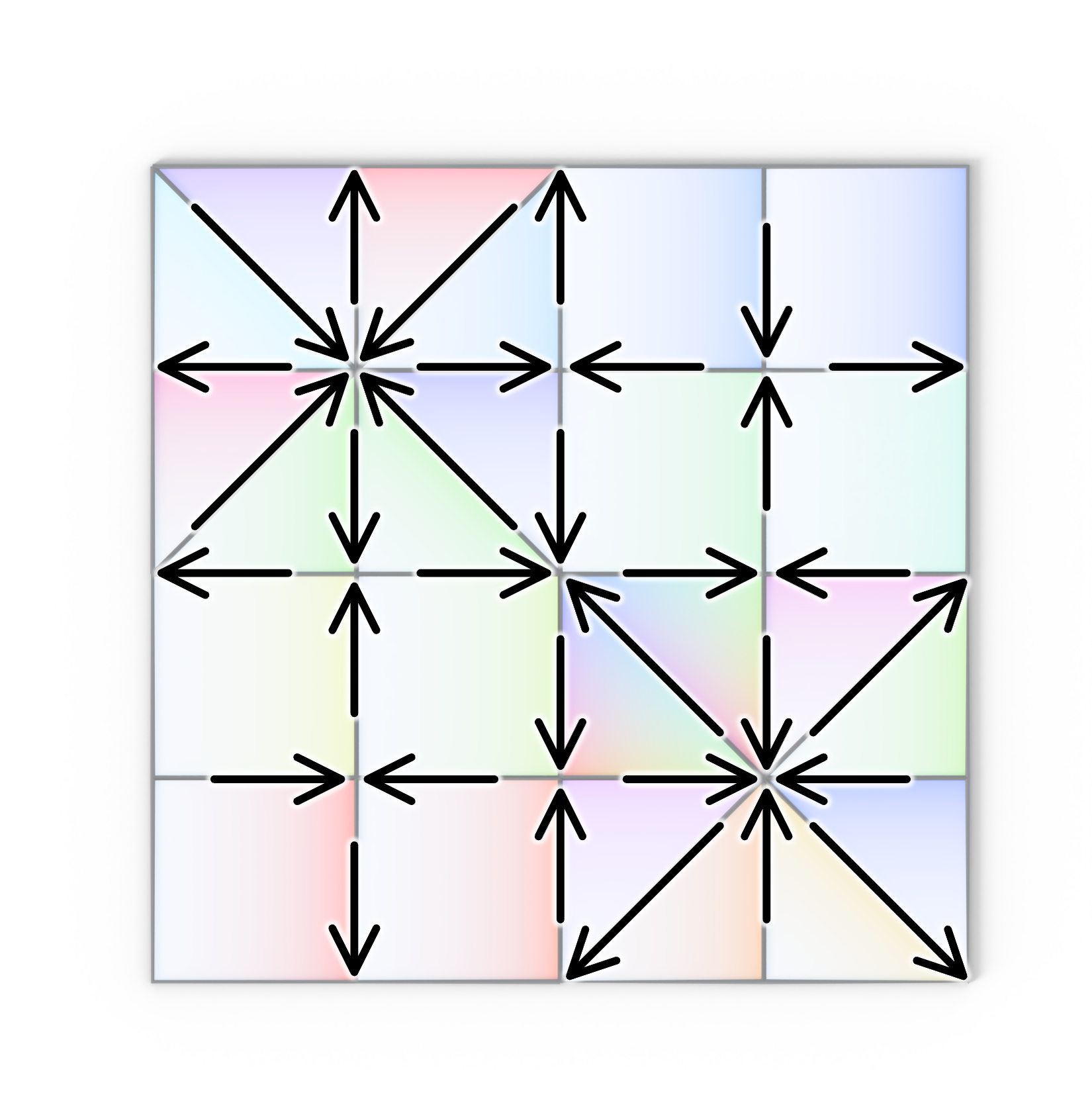
Note: the example on the left is uniformly deployable; its deployment is a one-parameter family of configurations parameterized by a single opening angle.
Core challenges
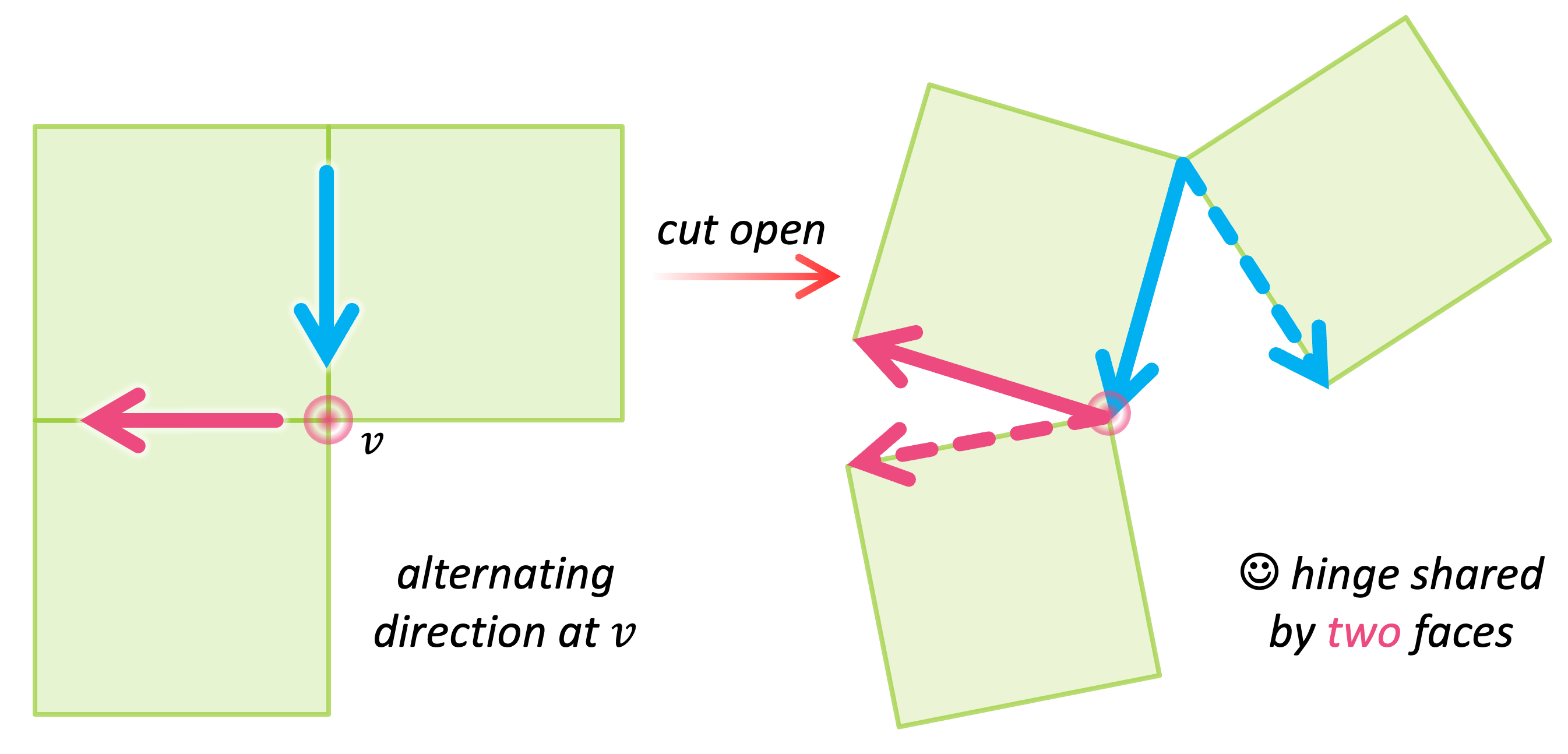
Note: to see why, consider the two adjacent cuts, they must have alternating directions to ensure that the hinge vertex after cutting is shared by exactly two faces. Please see Appendix A of our paper for the full proof.
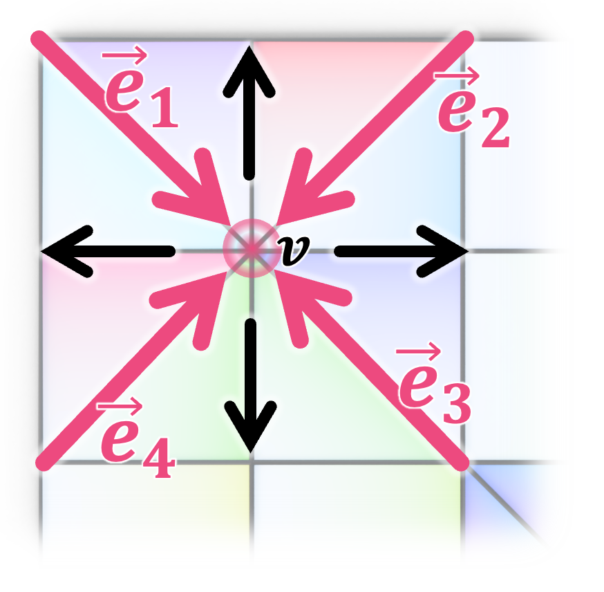
Note: the example on the left highlights a deployment-friendly vertex \(v\) with valency 8. The directed edges (cuts) ending at \(v\) are shown as arrows colored in red, and their vector sum equals \(\vec{0}\), satisfying the deployment-friendly condition.
Note: the proof is based on the assumption of rigid face rotation and planar deployment, so the holes between faces remain planar during deployment. Please see Appendix B of our paper for the full proof.
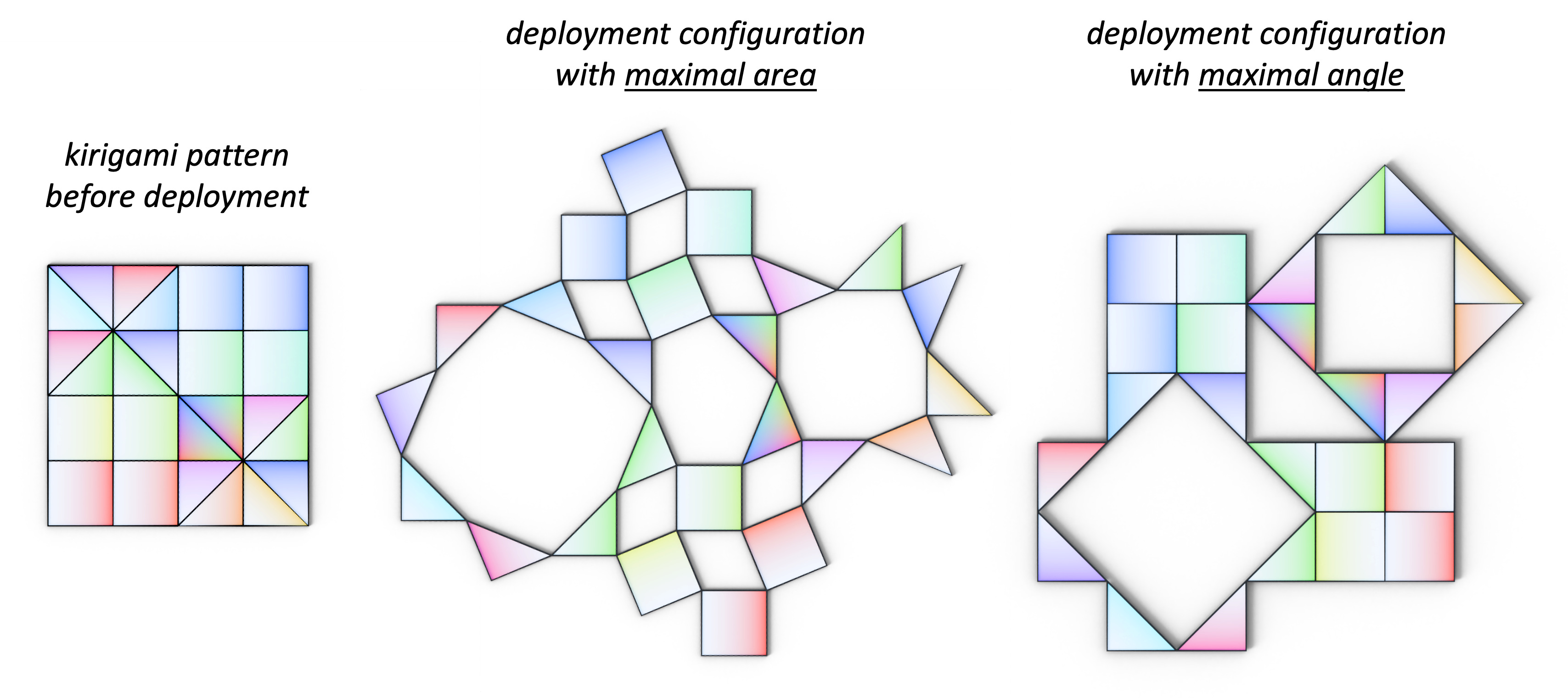
- maximal area expansion configuration can be obtained by optimizing \(\theta\) to maximize the area of the open kirigami pattern, accounting both for faces in the tiling and holes induced by cuts.
- maximal rotation angle configuration can be mathematically derived without optimization. Consider a hinge vertex \(v\) shared by two faces \(f_i\) and \(f_j\). Let \(\alpha_i\) and \(\alpha_j\) denote the internal angles at \(v\) for these two faces. The maximum opening angle allowed at \(v\) is \( 2\pi - \alpha_i - \alpha_j \). Rotating beyond this limit causes the faces to collide from the backside. Hence, the global maximum opening angle for the entire tiling is the minimum of these local vertex bounds; beyond this threshold, collisions are inevitable.
- It can be derived explicitly without optimization, whereas the maximal area configuration for unconventional patterns often requires optimization
- It provides intuitive fabrication instructions for deployment: rotate faces around hinges until they collide from the backside, rather than targeting specific angles
- It enables a new approach for programmable curvature to emerge from local combinatorial changes without holes (see examples below)
Algorithm Overview
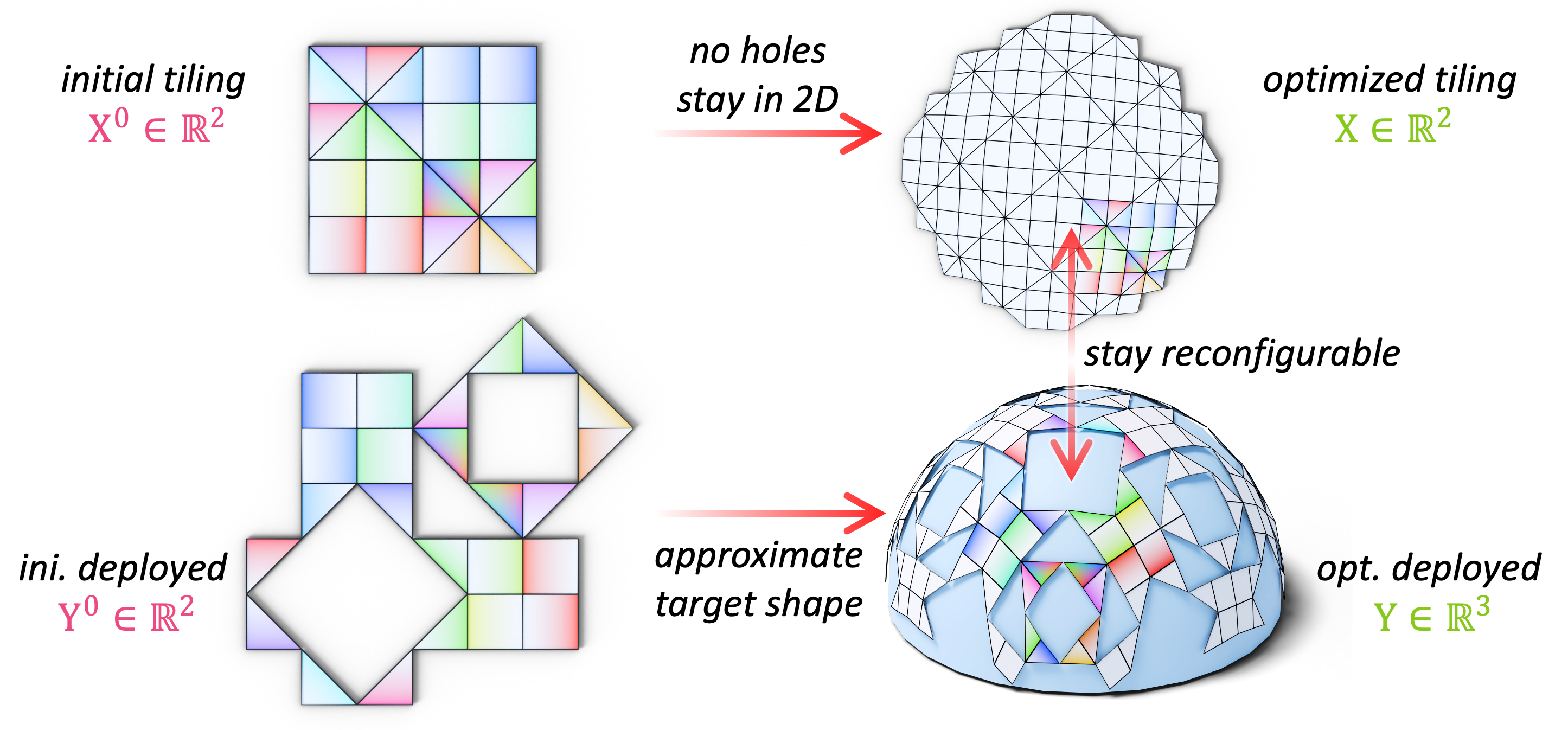
- input: a specified tiling pattern and 3D target shape
- output: optimized tiling with its
- 2D embedding \(\mathbf{X}\) before deployment
- 3D embedding \(\mathbf{Y}\) after deployment
- objectives:
- planarity: deployed faces (\(\mathbf{Y}\)) are planar
- reconfigurability: corresponding faces before and after deployment stay rigid
- shape approximation: 3D embedding after deployment well approximates the target geometry
- fairness: the optimized tiling does not deviate too much from its initial shape
- initializations:
- \(\mathbf{X}\) is initialized by \(\mathbf{X}^0\), which is given as input
- \(\mathbf{Y}^0\) is the deployed state of \(\mathbf{X}^0\), solved in Problem 2
- we parameterize the target geometry into 2D and get the flattening function \(f\). We then use \(f^{-1}\) to lift up \(\mathbf{Y}^0\), i.e., \(\mathbf{Y}^1 = f^{-1}(\mathbf{Y}^0)\in\mathbf{R}^3\) get the initial guess of \(\mathbf{Y}\)
Note: please see Sec.4.3 and Appendix E of our paper for more details about the optimization objectives and implementation. The source code can be find at here.